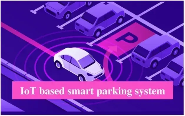
Smart parking system integrating Ultrasonic sensor and IoT
It is a solution to help the drivers to park their vechiles safely using ultrasonic sensor and IoT that constantly notifies via blynk app.
Abstract
Parking Assistant is a solution that assists drivers in parking their vehicles safely, using a variety of sensors that are strategically installed so that the entire parking process is safe and easy. Sometimes, drivers tend to hit the wall with their vehicles because they cannot see what is in their blind spots or underestimate how far the wall is from their back. The garage might also be too dark at times to safely park the vehicle. Therefore, building a system that can assist drivers by constantly notifying the distance between the back of the car and the wall, and can control the lighting, can help reduce this risk and assist them in parking their vehicles safely. An ultrasonic sensor, such as the HC-SR04, can detect the distance from the sensor to a distant object and can be used for this purpose. A safe limit can be set in the program, and if the vehicle is found to be closer than the safe limit, then the driver is notified about the risk through the buzzer. Additionally, using relays, an automated garage automation system can be created so that the electricals in the garage can be controlled through a simple mobile application.
1. Introduction
The number of cars owned by people has significantly increased over the past few years. Parking a vehicle safely is always a challenge because drivers have to continuously look in the rear-view mirrors, usually parking the car while guessing the distance between the back wall and the rear end of the car. This may sometimes lead to the back of the car hitting the wall, damaging the car. The driver could benefit from a device that continuously measures the distance between the wall and the back of the car and notifies him if he is about to strike the back wall. To further simplify the process of parking the car, the electronics in the garage can be automated so that everything in the garage can be controlled through a mobile application.
The objective of this project is to create a Garage Automation System, which constantly measures the distance from the back of the car to the wall while the driver is parking and notifies the driver about any potential risks. The system also enables the driver to conveniently control various appliances in the garage through a mobile application. The system consists of an HC-SR04 Ultrasonic sensor, which can accurately predict the distance between two objects, and utilizes a Relay, which can be used to remotely control the appliances. These sensors are connected to an ESP-32 Dev Module, which has Wi-Fi connectivity and thus can send or receive data wirelessly.
2.Literature Survey
2.1 Smart Parking: An Application of Optical Wireless Sensor Network
In most large cities, parking issues are a typical occurrence. Because parking is scarce, there is a resulting increase in air pollution, traffic congestion, and driver annoyance. Parking expansion costs are typically either prohibitive or excessively high. Recently, experts have focused on using technology to manage parking effectively. In prior work, they created an Optical Wireless Sensor Network (WSN) for traffic monitoring [1]. A wireless sensor network is a network of interconnected sensors that monitor and record conditions of the environment and store the data in a database. In a number of exhibits, this system has been shown to the general audience, and it is understood that this straightforward technology may be used to keep an eye on cars in a parking garage. If a car is occupying the parking space, it can be known based on the disruption in the readings of the Optical Sensor, and thus it can be known which parking spots are available for drivers to park their vehicles. Drivers can then be advised where to go and the number of parking spaces that are available by the system. Drivers shouldn't have to become frustrated trying in vain to find a parking space in a crowded parking garage thanks to this kind of system. Its drawbacks are as follows;
Due to the high likelihood of gadget failure, they are not accurate.
License plate detection cannot be performed with any degree of accuracy.
In addition, the size of the cars is projected, which is of little use.
2.2 Reservation-Based Smart Parking System
The challenge comes from not knowing where the open spots might be at that moment; even if they were known, several cars might chase for a small number of parking spots, severely clogging the road. In this study, a Reservation-based Smart Parking System (RSPS) prototype has been tested that enables vehicles to efficiently locate and reserve available parking spaces [2]. The reservation service is impacted by changes in the physical parking status through periodic learning of the parking status from the sensor networks installed in parking lots. Drivers are permitted to use their own personal communication devices to access this cyber-physical system. The experiment's findings indicate that the suggested reservation-based parking policy has the potential to streamline parking system operations and lessen parking-related traffic congestion. Its drawbacks are as follows:
Bluetooth's range is limited, making installation and maintenance challenging.
If the driver is inactive, the connection is lost, necessitating a new scheduling slot.
2.3 Smart Parking Assist System Using the Internet of Things
Automating the operation of the parking system that allocates a functional parking space is a clever and effective use of Internet of Things technology. The system has wireless connectivity thanks to the Internet of Things (IoT), which enables users to keep track of the parking lot's accessibility. The primary problem brought on by a rise in the number of automobiles in metropolitan areas is traffic congestion. The objective of this essay is to resolve this issue. Typically, the user wastes time and effort looking for a spot in a designated parking lot. A notification with parking details is sent to the user. As a result, the user spends as little time waiting as possible when seeking a parking space. An infrared sensor is used in this system. It is a similar system to the first system, but instead of optical sensors, infrared sensors are used. These sensors are usually cheaper and more accurate, as these signals can differentiate between the types of objects as well. Its pitfalls are as follows:
• Upon entering the parking lot, a driver could only determine if a spot was available; if none were available, the driver would have to leave, which could cause traffic congestion.
2.4 Automated Vehicle Parking System Using RFID
The automation of the vehicle parking system in a building or mall can greatly benefit from Radio Frequency Identification (RFID) technology[4]. Finding a parking spot can be a challenging issue for many car owners in large cities. Knowing the parking spot in advance will help you avoid wasting time and gas. The user of our system is informed of the parking spaces that are available at a specific parking spot. An RFID system is used to collect the slot availability information, which is then periodically updated in the database. RFID scanners, labels, and barriers will be used to manage the parking lots' entry and exit points. Using this technology will result in significant personnel cost reductions. A traffic jam problem will be avoided during these processes by handling entry and departure points quickly without having to stop the cars. The circulation points will not require drivers to stop, and parking tickets will not be valid at the entry and departure points. Because we added a recharge module, users must register in the system before they can receive balance notifications on their mobile devices. Additionally, issues with ticket processing equipment jamming will be eliminated. Vehicle owners won't be required to pay anything at each entry point, allowing for a speedier flow of traffic. Pollution will not be a problem because there won't be any queuing at entry points and exit points. Without changing the existing hardware, automated parking systems unquestionably lower the overall cost of the RFID parking system infrastructure. Its disadvantages are as follows:
The system's accuracy can be compromised if the tags are broken or if multiple tags are scanned simultaneously.
Ensuring proper tag functionality is crucial for reliable data capture and processing within the system.
Smart parking sensors, technologies, and applications for open parking IoT. Parking a car in a busy area frequently results in extra driving time spent looking for a spot, which causes traffic jams and environmental pollution. One cause of inefficient parking behavior is a lack of knowledge about available parking spaces. By guiding cars to available parking spaces, smart parking sensors and technologies increase parking effectiveness. Such sensors or technology are not currently used in open parking lots. This study examines the literature on smart parking sensors, technology, and applications and assesses how well they might be used in open parking lots. A few of the extensively utilized sensors and technologies on closed parking lots include magnetometers, ultrasonic sensors, and machine vision. Its drawbacks are as follows:
• This system has a wide variety of sensors, making its construction and maintenance extremely costly.
3. Proposed Method
To develop an efficient system to assist drivers, there are two key requirements. Firstly, the system should be able to accurately calculate the distance between the car and the wall, and also should be able to do this quickly, without consuming much time. To enable this, an ultrasonic sensor is used. An ultrasonic sensor is capable of calculating distances quickly and accurately, and is suitable for use irrespective of the conditions. It is perfect to use for this system. Secondly, there should be an efficient way to wirelessly control the appliances in the garage, to enable the automation aspect of the system. This method requires it to be reliable and efficient. For this, a relay is used, which is connected to an ESP32 microcontroller.
ESP32 microcontroller comes equipped with a Bluetooth and Wi-Fi module, which can be used to enable wireless control of the relay connected to it. For this system, we have chosen Wi-Fi, as it provides superior range and connectivity over the Bluetooth model. The power supply from the main source to the appliance is now broken and is passed through the relay. If the relay is in the OFF state, the circuit is incomplete, hence not allowing current to pass through and turning off the device. On the other hand, if the relay is in the ON state, the circuit is complete, and the device turns on. An interface is required to enable users to use this system by continuously monitoring the distance update and enabling garage automation access. For this, we used Blynk’s IoT interface. Blynk IoT provides us with many virtual pins, each of which can be mapped to a sensor to create data streams, through which data can be fed into Blynk’s cloud. Using Blynk’s IoT Android application, each data stream can be mapped to a widget – such as an OLED screen, a switch, a slider, etc. For this system, two widgets are used – an OLED screen to display the readings of the ultrasonic sensor in the application, and a switch – which is mapped to the relay – enabling wireless control over the relay to change its state. Additionally, a buzzer is attached to the ESP32 module – which makes a buzzing sound whenever the distance calculated by the ultrasonic sensor is less than the set threshold of 50 cm or 0.5 m away from the wall. The buzzer continues to sound until the distance calculated exceeds 0.5 meters.
These three parts are combined to create this system. Each part can be classified as a module - they function internally, as well as communicate with the other two modules, enabling flawless functioning of the system. The different parts of the system and their interactions are shown in Figure 1.
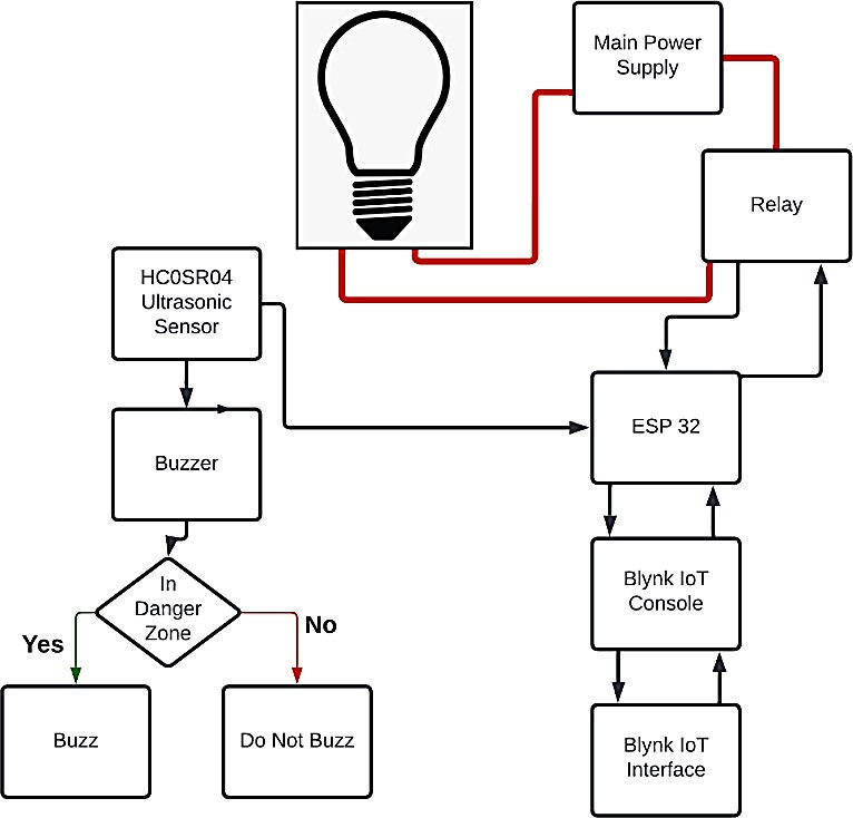
Fig. 1. Architecture diagram of the parking system.
For the implementation of the project, there are 3 modules that should be worked on. They are:
Ultrasonic Sensor Module
Electrical Components Module
User Interface Module
1.Ultrasonic sensor module
An ultrasonic sensor sends an ultrasonic wave, which travels and hits the object in front of it. The reflection of the wave is caught by the receiver, and the time taken for the journey is noted. The speed of the ultrasonic wave is known beforehand, and the distance is calculated. This distance is sent to the Blynk Console through Wi-Fi and is also used to check whether the distance is in a safe proximity or not. Based on the conditions, the buzzer is activated.
2.Electrical Components Module
The connection from the main power supply is broken and attached to the relay. The relay can then be controlled through the Blynk IoT interface using Wi-Fi or Bluetooth, based on the scenario. Based on the input from the user, the relay is either turned on or off, thus either completing the circuit or breaking it.
3.2 User Interface Module
The data from the Ultrasonic sensor and the Relay are both connected to the Blynk console using two separate data streams. The data received from the Ultrasonic sensor is displayed on the LCD component in the Blynk Interface, and the data stream from the Relay is connected to a switch component which maps to two values – 0 and 1. 0 corresponds to the OFF state and 1 corresponds to the ON state. Based on the status of the switch, data is transmitted to the ESP32 board, and the relay state is changed accordingly.
4 Results and Discussion
4.1 Ultrasonic sensor module
The functionality of this module is to constantly measure the distance from the sensor to the object and update it every second. The values recorded are then used for two purposes: to check whether the distance is within the limits, display this value in the serial monitor, and also to the user via Blynk IoT Interface. The ultrasonic sensor calculates the distance based on two parameters: (i) The time taken for the round trip of the ultrasonic wave and (ii) The speed of the ultrasonic wave. (The speed of the ultrasonic wave is approximately equal to the speed of sound (~340 m/s)). If the wave completes the round trip in 2 microseconds, then the distance would be calculated as (speed * time)/2 i.e. (340*2*10^-3)/2, which is 0.34 meters, or 34 cm. The values output from the sensors are as shown in Figure 2.

Figure 2. Readings from the Ultrasonic sensors
The ultrasonic sensor calculates the distances in centimeters. This can be seen in the serial monitor in Arduino, as shown in Figure 3. Based on observation, the safe parking distance from the back wall to the car is noticed to be 50 cm or 0.5 m, which is set to be the threshold value. The distance calculated by the ultrasonic sensor is checked, and if the distance is below 50 cm, then the buzzer is activated, and it remains activated until the distance exceeds 50 cm.The activation of the buzzer is depicted by displaying the word “Buzzer” in the serial monitor whenever the condition is met. This can be seen in Figure 3.

Fig. 3: Buzzer activation based on reading from ultrasonic sensor.
4.2 Electrical Components Module
This module consists of a relay, which is connected in between the connection from the main power supply unit. The relay here acts as a switch, which can either complete the circuit or break the circuit depending on the state of the switch, as controlled by the user from the Blynk Interface. The application switch has two states – ON and OFF. ‘ON’ state supplies 1 as an input to the relay, which indicates it completes the circuit and closes the loop, whereas the ‘OFF’ state supplies 0 as an input to the relay, which indicates it breaks the circuit. This change of states can be shown in the serial monitor by displaying its current state as 0 or 1. These inputs are supplied to the relay from the Blynk console, via the Wi-Fi module of the ESP32 board, thus enabling wireless control of appliances.This can be seen in Figure 4.
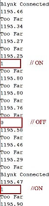
Fig. 4: Relay output based on reading from ultrasonic sensor.
4.3 User Interface Module
This module is responsible for providing the interface for the user to communicate with the system. The users are provided with an interface consisting of a button and an LCD screen. The button can exist in two states – each of these states is responsible for a particular configuration of the relay. The LCD screen shows two lines of output – the first line shows the category to which the distance belongs, and the second line shows the distance from the sensor to the back of the car in meters. This interface should not be too complicated; it is supposed to be as simple as possible. A sample of the interface is shown in Figure 5. The LCD screen is updated every second, as the value is measured every second by the Ultrasonic sensor and sent to the console. Therefore, a real-time view is provided for the user. The screen shows four types of values. When the vehicle is too far from the ultrasonic sensor, or it is out of range from the sensor, the screen shows the default value (11.97 m) as seen in Figure 5(a). If the vehicle is within the range of the sensor, then the corresponding values are displayed in meters, along with the category in which the distance falls i.e., Far, Close, and Too Close, as shown in Figure 5.

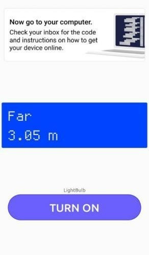

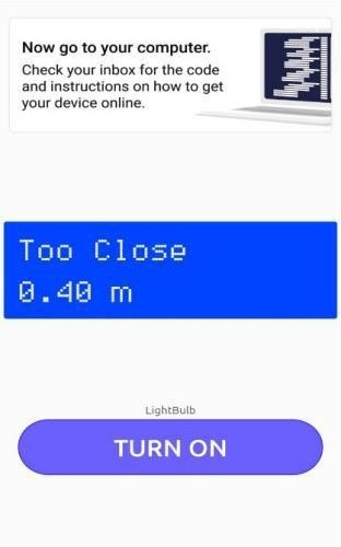

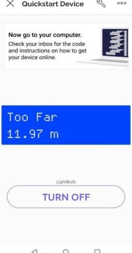

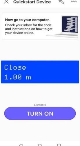
Fig. 5. Blynk IoT interface.
5.Conclusion
This system uses an ultrasonic sensor to provide accurate and real-time updates to the driver. One major advantage of this system is its ability to function irrespective of the vehicle. This system is a cheap and easy-to-use option and can be used by any vehicle owner. However, there are still some improvements to be made. We aim to include the following features in later iterations of our project. This system currently only has a single ultrasonic sensor, which is used to provide rear-distance updates to the user. Though this is advantageous, multiple ultrasonic sensors can be incorporated into this system to enable the driver to get an all-around overall view of the surroundings on their smartphone. For this to function, a good option would be to put the sensors on the body of the car itself because, unlike just the rear sensor where the motion would just be in a single straight line, the sensors on the sides have to read the distances even if the car travels in a curvilinear path. This system can only connect one electrical appliance to the smartphone. However, this is not the case, as 5 more relays can be connected to the board, allowing us to control as many as six appliances from a single ESP32 board. Additionally, using a port expansion chip such as the MCP23017 I/O expander can add up to 128 I/O pins, enabling us to add up to 128 relays which can be controlled individually.
References
[1] J. Chinrungrueng, U. Sunantachaikul, and S. Triamlumlerd, Smart Parking: An Application of Optical Wireless Sensor Network, in the Proceedings of the International Symposium on Applications and the Internet Workshops (2007)
[2] H. Wang and H. Wenbo, A Reservation-based Smart Parking System, in the Proceedings of the IEEE Conference on Computer Communications Workshops (INFOCOM WKSHPS) (2011)
[3] Smart Parking Assist System using Internet of Things (IoT), International Journal of Control Theory and Applications, Volume 9, Number 40, 2016
[4] C. Lee, Y. Han, S. Jeon, D. Seo, and I. Jung, "Smart parking system for Internet of Things," in the Proceedings of IEEE International Conference on Consumer Electronics (ICCE), Las Vegas, NV, USA (2016)
[5] S. C. Hanche, Pooja Munot, Pranali Bagal, Kirti Sonawane & Pooja Pise, ITSI Trans. on Elec. and Electr. Eng. (ITSI-TEEE), 1, 2 (2013)
[6] P. Vijay, F. Hasan, H. Johan, Roger G. Nyberg, IET Intelligent Transport Systems, 12, 8 (2018)
project gallery
 |  |  |  |
|---|---|---|---|
 |  |